Coupled-line microstrip bandpass filters are easy to design for narrow bands but for relatively large band it becomes complex as more parameters are need to be considered. Odd mode Loss 00740294.

Design Coupled Line Bandpass Filter Part 2 Simulation Youtube
A band pass filter lets only a certain frequency band pass through and attenuates frequencies below and above.

. Even mode Losslen 00808908. Design for Strip-Line Band-Pass Filters. -coupled There are also several implementations in addition to the microstrip medium including stripline coplanar waveguide and slotline.
This paper presents the design and test of a planar coupled line filter constructed from relatively high quality dielectric material. V g L 11 L 21 C 21 C 31 L 31 11 C 1 1. Design Coupled Line Bandpass Filter Part 1.
Band Pass Filter Calculator. Coupled line filter a layout of a typical N1 section of coupled line band pass filter and b its equivalent circuit. GN1 are used to find the admittance inverters impedance.
Designed topology is converted into band pass using standard transformation equations. Design Equations for Coupled Line Filter To design coupled band pass filter a low pass filter prototype is selected For the required roll off five sections are selected. FABRICATION OF FILTER For filter fabrication double sided coated PCB is used with thickness h 0762 mm and relative permittivity 32.
On Microwave Theory and Techniques 5. Interdigital and parallel-coupled-line filters are traditional coupled-line structures to implement bandpass filter. Listing Results about Edge Coupled Microstrip Impedance Calculator Medical.
In addition to the formulas you will find handy band pass calculators for easy calculation of the filter. Project the structure of parallel-coupled mirostrip bandpass filter will be design and simulate using Ansoft Designer software before it goes to the fabrication process. A basic coupled line filter using high quality material can achieve the desired specification.
Note that X or em-based models are used wherever possible for better accuracy in the filter design. Passband insertion and return loss is. Filter design as with most RF design is a combination of art and science.
Cross coupled Planar Microwave Filters IEEE Transaction on Microwave Theory and Techniques Vol. Part B 8 Filter design is based on circuit transformations. Further lumped sections are converted into distributed elements using Richards.
The low cost ease of design and good performance will. Coupled-line filter is a good choice for the design of microstrip bandpass filter 1. The bandpass coupled line filter presented here is specified to have a midband at 169GHz and bandwidth of 0169GHz.
This filter design approach is based on decreasing the coupling gap between adjacent resonators of a parallel-coupled-line bandpass filter in order to achieve both the desired multiband frequency. The cover height HU of the substrate is. The prototype filter is composed of quarter-.
Strip-line band-pass filters can be constructed either of half-wavelength strips capacitively coupled end-to-end as shown in Fig. The MWO Transmission Line Calculator Next a schematic diagram of the filter is constructed as in fig 3. Interdigital Band pass filter is designed and simulated by Finite Element.
1 or using parallel coupling of the half-wavelength strips as. Parallel Coupled-Line Combline Filter. The source for these formulas are found in the IPC-2141A 2004 Design Guide for.
The UWB bandpass filter operating in the 36 GHz to 106 GHz frequency band is targeted to comply with the FCC spectral mask for UWB systems. Yun and D Ahn A design of the novel coupled-line band pass filter using defected ground structure with wide stop band performance IEEE Trans. In this part of the tutorial lesson you will cascade four quarter-wavelength Generic Coupled T-Line segments to build a distributed bandpass filter as shown in the opposite figure.
A tapped structure is chosen for the external couplings. Show full abstract conventional parallel coupled line bandpass filter has also been implemented with exactly same design goals for the sake of comparison. Strip widths and gap spacings are given in graphical form for band-pass filters using symmetrical strip lines.
When it comes to GHz frequency range the coupled-line microstrip bandpass filter is. Layout design of parallel-coupled line bandpass filter with N5 in design editor of Serenade. Design of Microstrip Coupled Line Bandpass Filter Using Synthesis Technique 1PPriyanka 2DrSMaheswari 1PG Student 2Professor Department of Electronics and Communication Engineering Panimalar Engineering CollegeChennai India AbstractIn this Paper aim is to achieve a narrow bandwidth filter.
This article shows you different circuit variants of passive bandpass filters. INTRODUCTION Parallel coupled transmission-line filter in microstrip and stripline technology are very common for implementation of bandpass and band-stop filters with required bandwidth up to a 20 of central frequency. Section of coupled line filter takes the form shown in Fig.
For that coupled line filter is good choice. General structure of parallel edge-coupled microstrip Bandpass filter. Then the low pass prototype elements g0.
Designing a Coupled Line Bandpass Filter. The design and performance of parallel-coupled microstrip bandpass filter will. Design of Coupled Line Bandpass Filter Firstly the order N of the filter is determined by Insertion loss method.
Port 1 of the first segment and Port 4 of the last segment are designated as the input and output ports. Generally coupled line inputs are fine for narrow band. Design of Coupled Line Bandpass Filter.
Popular and relatively practical to design. 22 Filter parameters When dealing with filters the following parameters plays an important role 2-3 8. In this thesis ultra-wideband UWB microwave filters and design challenges are studied anda microstrip UWB filter prototype design is presented.

Rfdude Com Llc
Rf Tutorial Lesson 7 Designing Distributed Bandpass Filters Using Coupled Transmission Line Segments Emagtech Wiki
Rf Tutorial Lesson 7 Designing Distributed Bandpass Filters Using Coupled Transmission Line Segments Emagtech Wiki

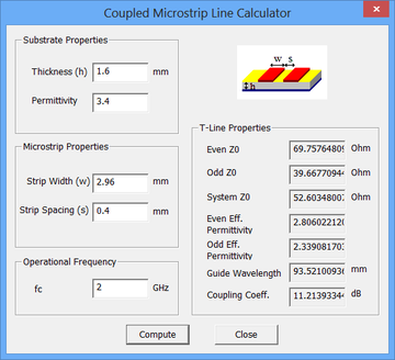
Parallel Coupled Band Pass Filter Calculator First Interface Download Scientific Diagram
Schematic Circuit Of Parallel Coupled Microstrip Bpf With Agilent Ads Download Scientific Diagram

1 Parallel Coupled Band Pass Filter At 3 2 Ghz Results Using Tool Download Scientific Diagram

1 Parallel Coupled Band Pass Filter At 3 2 Ghz Results Using Tool Download Scientific Diagram

Figure 1 From Parallel Coupled Line Bandpass Filter Design Using Different Substrates For Fifth Generation Wireless Communication Applications Semantic Scholar
0 comments
Post a Comment